| Tuning a DPF 2/6 H Procom Six cavity VHF duplexer |
|
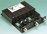
This duplexer is designed to connect one transmitter and one receiver to a single VHF antenna.
It is built with 6 tunable cavities. One set of 3 cavities will block the low frequency, the other set of 3 cavities will block the high frequency. Let see how we can tune this duplexer and what can be achieved when using the miniVNApro and the DL2SBA vna/J software. |
|
Installation setup: For example; we have a repeater made with two radios. The transmitter (165 MHz) is connected to the port marked ''HIGH'', and the receiver (160 MHz) is connected to the port marked ''LOW''. The antenna is connected to the port marked ''ANT''. |
Software setup: Start the miniVNA/J software. Select the ''transmission'' mode. Make sure your miniVNA is correctly calibrated. Set the start frequency at 155 MHz and the stop frequency at 170 MHz, this will gives you a display scan span of about 15 MHz. Set the ''Marker-1'' at 160 MHz and the ''Marker-2'' at 165 MHz. Using the ''transmission'' mode, tick the ''freerun check box''. On the top left drop down list select ''TL (dB)'' and on the top right list select ''none''. Do not modify/change those settings any more until you finish the job. |
1/ Tuning the 3 transmitter cavities: |
|
- Connect the miniVNA 'DET' port to the duplexer ''ANT'' connector. - Connect the miniVNA 'DUT' port to the duplexer ''HIGH'' connector. - Connect a 50 Ohm dummy load to the duplexer ''LOW'' connector. With a flat screw driver, tune the 3 concerned cavities in order to obtain a maximum rejection on 160 MHz (Marker-1) together with a minimum loss at 165 MHz (Marker-2). A good result is to have the 'TL' values around -1dB or less on 165 MHz and more than -80 dB on 160 MHz. Try to achieve something like shown in the graph below or better. |
 |
| 2/ Tuning the 3 receiver cavities: | |
|
- Connect the miniVNA 'DET' port to the duplexer ''ANT'' connector. - Connect the miniVNA 'DUT' port to the duplexer ''LOW'' connector. - Connect a 50 Ohm dummy load to the duplexer ''HIGH'' connector. With a flat screw driver, tune the 3 concerned cavities in order to obtain a maximum rejection on 165 MHz (Marker-2) together with a minimum loss at 160 MHz (Marker-1). A good result is to have the 'TL' values around -1dB or less on 160 MHz and more than -80 dB on 165 MHz. Try to achieve something like shown in the graph below or better. |
|
 |
|
You can repeat the operation (1) and the operation (2) to get the strongest rejection possible and the weakest insertion loss. When finish, reconnect the radios and antenna. |
|
- Procom duplexers and filters website - MiniVNA menu page. |